Energy Logging
Logging hardware and custom code
Introduction
Energy consumption is calculated using six current sensors in the electrical panel, which feed into two network-connected interface boards.
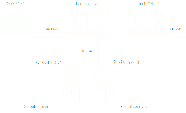
The current sensors feed values back to the Arduinos, which feed them to Router A. Router A passes the values on to the server, which logs them in Home Assistant.
Power Supply
To provide both Arduinos with a strong power supply, as well as the temperature logger, and to leave excess capacity for future expansion, I installed an ATX power supply from a desktop PC. They are designed for continuous operation in computers and are typically very stable and reliable. It is built to handle fluctuating loads and provide consistent 20A at 3.3v, 20A at 5v and 40A at 12v DC.
Arduinos
Again, open source. The Arduinos are both stacked with ethernet and energy monitoring shields. Each energy monitoring shield can support four current sensors.
Both Arduinos run my own custom code. In basic terms, the code is repeatedly:
- Reading current
- Reading voltage
- Calculating power
- Broadcasting data
Importantly, the broadcast of data between the Arduinos and Home Assistant uses the MQTT protocol. This is an open source protocol, meaning that the system is now open source from one end to the other, and protected from vendor lock-in.
Current Sensors
The current sensors are available in a variety of ratings, and it is important to choose one that operates within its optimal range. A sensor rated too low may become overloaded, while one rated too high may have reduced resolution and lower signal-to-noise ratio, leading to less accurate readings. For example, a 32A load should be monitored with a 50A sensor, not a 100A.
I am monitoring the five high-usage circuits of the 17 in my electrical panels:
- Sockets
- Microwave
- Washing machine
- Oven
- Immersion
With a sixth sensor on the main incomer measuring total energy consumption, I can calculate the energy used by low-power circuits—such as lights, smoke detectors, and other small devices—by subtracting the sum of the five high-usage circuits from the main incomer. This approach is not only simpler and more cost-effective but also significantly more accurate than attempting to measure minor currents individually. Using 11 individual 50A sensors to monitor very low-power circuits would result in considerable inaccuracies due to operating well below the sensors’ optimal range. Moreover, knowing the power usage of each individual lighting circuit is unnecessary.
Calibration
Once the system is running, each sensor needs to be calibrated. For greatest accuracy, it should be connected to the largest, most consistent known load available that falls within the sensor’s operating current range. Conveniently, my heat pump control unit displays instantaneous power usage. By knowing this actual power usage, the existing calibration value, and the value being broadcast by the Arduino (which is calculated using the calibration value), the necessary adjustment to ensure the broadcasted value matches the actual power usage can be determined: